이 튜토리얼은 Eclipse Modeling Framework (EMF) 와 Graphical Editing Framework (GEF) 사이에 generative 연결을 제공하는 Eclipse Modeling Project 인 Graphical Modeling Framework (GMF) 을 소개할 것이다.
이 튜토리얼에서는 여기에 설명되어 있는 mindmap 어플리케이션을 개발할 것이다. 이 튜토리얼은 2.0.1 빌드 를 사용하여 GMF가 현재 제공하고 있는 기능에 대해 설명한다. It is expected that this tutorial will evolve with GMF to introduce new functionality as it is developed. New functionality will be covered by installments added to this tutorial, each with a corresponding viewlet. A viewlet for this installment of the tutorial can be found here (warning: it's a bit out of date). 이 튜토리얼의 전체 솔루션은 CVS 에서 유지보수 되고 있다.
목차 |
Overview of GMF
Eclipse 기반의 기능을 만들기 위해 EMF 와 GEF 를 함께 사용하는 것이 매우 일반적이다. 아래의 많은 레퍼런스는 이 프레임워크를 함께 활용하는 방법에 대한 정보를 제공한다. 일부는 GMF 프로젝트 자체에 대한 것이다. GMF 프로젝트에 뛰어들기 전에 먼저 GMF가 generative 방법으로 EMF 와 GMF 를 이용하는 태스크에 접근하는 방법에 대해 간략하게 살펴볼 것이다. GMF 의 런타임에 초첨을 둔 글은 여기서 볼 수 있다.
'practitioner' 가 플러그인을 활용하는 개발자를 언급하기 위해 사용되기 때문에, GMF 를 사용하여 플러그인을 만드는 개발자를 언급하기 위해 GMF 프로젝트는 'toolsmith' 용어를 도입했다. 사용성의 관점에서 GMF 에 의해 활용되는 'models' 의 종류와 수는 최대한 내부적을 숨겨야 한다. 하지만 대부분의 toolsmith 는 아래에서 무엇이 진행되는지에 대해 관심이 있다. 그래서 각 모델에 대한 설명이 GMF Documentation 페이지에 링크되어 있다.

이 다이어그램은 GMF 기반으로 개발할 때 주로 사용되는 컴포넌트와 모델을 보여준다. GMF 의 핵심은 그래픽 정의 모델 개념이다. 이 모델은 GEF 기반의 런타임에서 보여지는 그래픽 요소와 관련된 정보를 담고 있다. 하지만 표현과 편집을 제공하는 도메인 모델로의 직접적인 연결이 있는 것은 아니다. 추가적인 툴링 정의 모델은 팔레트와 다른 메뉴나 툴바 등을 설계하는데 사용된다.
몇 개의 도메인에서는 그래픽 정의와 툴링 정의가 동등하게 잘 동작할 것이라 생각된다. 예를 들어, UML 클래스 다이어그램은 기본 구조와 외관이 매우 유사한 많은 카운터파트를 갖고 있다. GMF 의 목표는 여러 도메인에서 재사용되는 그래픽 정의를 허용하는 것이다. 그래픽 정의와 툴링 정의를 연결하는 모델과 선택된 도메인 모델의 매핑을 사용하면 목표를 달성할 수 있다.
일단 적절하게 매핑이 정의되면, GMF 는 생성 단계를 위해 정의된 세부 구현을 허용하는 생성자 모델을 제공한다. 생성자 모델 기반의 편집기 플러그인의 생성은 최종 모델, 즉 다이어그램 런타임(또는 "notation")을 목표로 한다. 런타임은 사용자가 다이어그램으로 작업할 때 notation 과 도메인 모델을 연결할 것이다. 또, 그 둘의 동기화를 제공하며, 지속 가능하게 할 것이다. 이 런타임의 중요한 점은 EMF 와 GMF 기능으로 서비스 기반의 접근 방식을 제공한다는 것이다. 그리고 생성되지 않는 어플리케이션에서도 활용 가능하다는 점 역시 중요하다.
이제 특정 도메인을 위한 그래픽 편집 suface 의 개발에서 GMF 를 사용하는 절차에 대해 알아보도록 하자. 먼저, GMF 와 관련 플러그인을 설치할 필요가 있다.
Setup

이 튜토리얼은 GMF 빌드 2.0.1 을 사용하여 작성되었다. GMF 설치 전에 설치되어야 하는 것들은 빌드 페이지, download 페이지, 업데이트 매니저 site 에 나열되어 있다.
GMF 를 시작하는 가장 쉬운 방법은 새로운 Platform 으로 시작하여 Europa 업데이트 사이트를 활용하여 설치하는 것이다. Help > Updates > Find and Install... 으로 업데이트 사이트에 접근할 수 있다. Search for new features to install > Europa Discovery Site. 그리고 'Models and Model Development' 카테고리의 하위 항목인 Graphical Modeling Framework (Europa Edition) 를 선택하라. 그 후 GMF 가 의존하고 있는 플러그인 설치를 위해 'Select Required' 버튼을 클릭해라. 참 쉽죠?
아래에 참조되어 있는 TaiPan 예제는 CVS 에서 유지보수 되고 있고, 튜토리얼이 최신 버전이 아니더라도 GMF의 최신 빌드에서 동작해야 한다.
Quick Start

GMF 의 동작 모습을 모고싶다면 Taipan 예제 프로젝트를 CVS 에서 워크스페이스로 체크아웃해라. 이미지처럼CVS Repository Exploring 퍼스펙티브로 전환하고, repository 위치를 추가하라. 그렇지 않으면 다음 섹션을 뛰어 넘어도 된다.
/HEAD/org.eclipse.gmf/examples 로 가서 org.eclipse.gmf.examples.taipan.* 모듈을 선택하라. 우클릭하여 체크아웃 메뉴를 선택하라. 최신 빌드와 GMF 의 prerequisite 을 사용하지 않는다면, 사용하고 있는 버전에 맞는 Taipan 버전을 체크아웃하라. 중요한 점은 GMF SDK 와 Taipan 예제의 버전을 동기화 하는 작업이 필요하다는 것이다. 이 것을 위해 체크아웃이 끝나면 프로젝트를 우클릭해서 'Team | Switch to Another Branch or Version...'를 선택할 수 있다. 그리고 'Select the tag from the following list'를 선택하고 GMF 2.0.1 을 배포한 날짜인 2007년 9월 28일 입력하기 위해 바닥에 있는 'Add Date...' 버튼을 사용하라. Finish 버튼을 클릭하면 설정이 완료된다.
플러그인 개발 퍼스펙티브로 가서 org.eclipse.gmf.examples.taipan 프로젝트의 models 폴더를 열어라. 여기에 있는 model 을 살펴보고 element property 도 살펴봐라. You'll notice that there are full and RCP versions of the generated Taipan examples to explore.
튜토리얼에서 각 모델을 차례로 살펴볼 것이다. 환경 설정을 검증하라. 런타임 워크스페이스에서 이 예제를 실행할 수 있어야 한다. (simply accept the defaults for a new 'Eclipse Application' run configuration). 런타임 워크스페이스에서 빈 프로젝트와 새로운 New 다이얼로그의 Examples 폴더에 있는 'TaiPan Diagram' 을 생성하라. 원하는 이름으로 설정하고 Finish 를 클릭하라. 생성된 다이어그램 편집기가 열려야 한다. 특별히 기억해야 하는 것은 아래와 같다:
-
- tool palette and overview
- layout and selection tools
- diagram image export (svg, bmp, jpeg, gif)
- tabbed properties view
- font and color options for selected element
- link routing and style options
- pop-up bars and connection handles
- notes and geometric shapes
- animated zoom and layout
- diagram printing

TaiPanApplication 을 실행하기 위핸 새로운 launch configuration 을 생성하고 Taipan 을 standalone RCP 다이어그램 펀집기로 실행시키기 위해 Plug-ins 탭에서 Taipan *.rcp 플러그인과 dependency 를 선택하라.

이것으로 튜토리얼의 quick start 가 끝났다. 다음은 mindmap modeling surface 의 생성에서 본 모델에 대해 더 자세하게 살펴볼 것이다.
A New Project
시작하기 전에 컴파일러를 1.5로 설정해야 한다. Window... Preferences... Java...Compiler 옵션에서 1.5 의 Compliance Level 을 선택했는지 확인하라.
여기서 설명된 것처럼, GMF 를 이용한 시나리오 중 하나는 마인드맵 어플리케이션을 위한 그래픽 surface 생성을 포함한다. to eventually be complemented with an alternative view of its temporal information (likely a Gantt chart - feel free to contribute this to the wiki). 이 섹션의 마지막에서 GMF 의 가능성을 보여줄 것이고, 프로젝트가 진행됨에 따라 계속 발전할 것이다. 이 튜토리얼을 진행하기 전에 전체 솔루션을 보여주는 프로젝트를 보고 싶다면 CVS 의 org.eclipse.gmf/examples 모듈에서 마인드맵 프로젝트 세트를 받을 수 있다. 모든 마인드맵 프로젝트를 선택했다면, 프로젝트를 컴파일하기 위해 Experimental SDK 를 설치해야 할 것이다.

'Help | Cheat Sheets...' 메뉴로 Tutorial Cheat Sheet 에 접근할 수 있다. (Note that if you've installed GMF onto a platform without the SDK, i.e. using Europa's update manager, you will need to open the Cheat Sheets view from the Window | Show View... | Other... menu and then open the GMF Tutorial Cheat Sheet from the view menu). If you open this cheat sheet 을 열어서 각 단계를 따라하면 튜토리얼의 처음 부분을 거의 이룰 수 있을 것이다. while taking advantage of some actions that will launch and pre-populate wizards to get you started. 새 프로젝트를 생성하기 위해 이 것을 시도해보라.
또는 New 다이얼로그 (Ctrl+N) 에서 'Graphical Modeling Framework' 아래의 "New GMF Project" 메뉴로 생성할 수도 있다. 프로젝트 이름은 'org.eclipse.gmf.examples.mindmap'로 하고 루트에 'model' 폴더를 생성하라.
Domain Model Definition
Although it may seem necessary to begin with the domain model, it is not in the case with GMF, as the diagram definition is maintained separate from the domain. However, we will begin with the domain in the tutorial as it is likely familiar to most, and will allow us to jumpstart our diagram definition from the domain model using a wizard in the next section.
A basic domain model for our mindmap is found in an Ecore version here. Following the cheat sheet, in the section "Domain Model", select the Model Importers ... Ecore Model .... On the next panel, copy the URL from the download link found on the Ecore file and select the "Load" button.
(Alternatively, you may start with an XSD of the mindmap model, found here (you'll need to install the XSD feature from EMF in this case). Copy this file into your 'model' folder and feel free to examine the model, if you wish. GMF provides a (bootstrapped) graphical editor to complement the standard EMF generated editors, and is packaged in the SDK.
To render the mindmap.ecore (or any *.ecore model) with the editor, simply right-click the file and select 'Initialize ecore_diagram diagram file' from the menu.

To continue, create a new mindmap.genmodel from the mindmap.ecore file using the New > Eclipse Modeling Framework > EMF Model wizard. You may wish to change the 'Base Package' property for the genmodel's 'Mindmap' package to org.eclipse.gmf.examples to have your generated packaging match the project name. These steps are also covered in the next step of the cheat sheet.
Generate the model and edit code using the right-click menu available from the root of the generator model. There is no need to create an editor or tests, but you are welcome to do so if you'd like. Now, we're ready to begin creating the graphical and mapping definitions for our mindmap application.
Graphical Definition

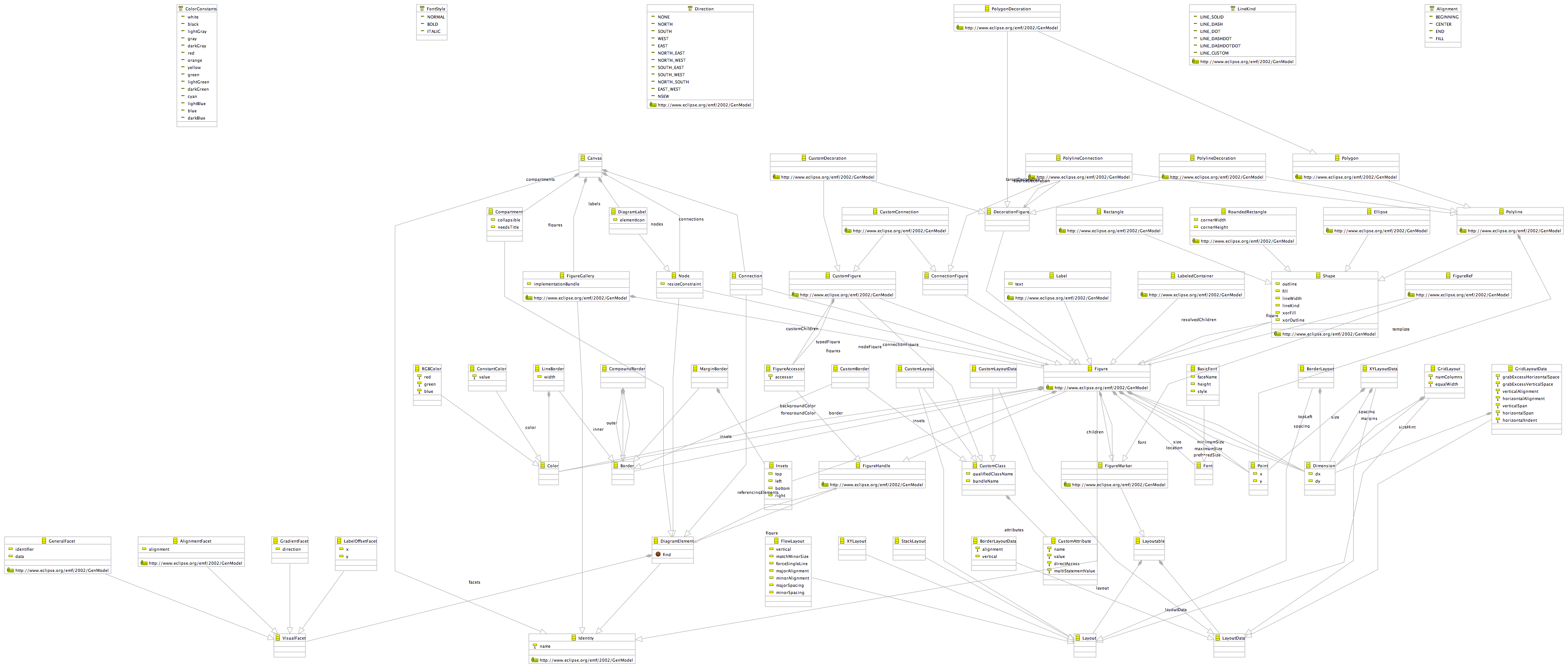
A graphical definition model is used to define the figures, nodes, links, etc. that you will display on your diagram. The model you will work with to do this is seen at the right.
Continuing on with the next step in the cheat sheet, we will create a new graphical definition model. The cheat sheet will launch the Simple Graphical Definition Model wizard, which is found in the Graphical Modeling Framework folder of the New (Ctrl + N) dialog. Select the 'model' folder under your org.eclipse.gmf.examples.mindmap project for the mindmap.gmfgraph model, and on the next page of the wizard use 'Browse' to locate your mindmap.ecore file. Select our Map class as the Diagram element.
On the last page of the wizard, select a minimal set of element, link, and label options for our Topic class as shown in the image. Later on, feel free to experiment with this wizard and observe its output. For now, we're just interested in getting a minimal set of models to get started. Click 'Finish' to complete.
If you examine the model, you will find a Canvas at the root with a Figure gallery containing basic Rectangle, Label, and Polyline Connection elements. These are used by corresponding Node, Diagram Label, and Connection elements to represent our Topics from the domain model. We can leave the defaults as-is for now and continue with our tooling definition in the next step of the cheat sheet.


Tip : There are several figure galleries intended for reuse and included with GMF. You can load these into your *.gmfgraph model (or *.gmfmap model) by using "Load Resource..." and enteringplatform:/plugin/org.eclipse.gmf.graphdef/models/basic.gmfgraphfor the Resource URI. Others available includeclassDiagram.gmfgraphandstateDiagram.gmfgraph.
Tooling Definition

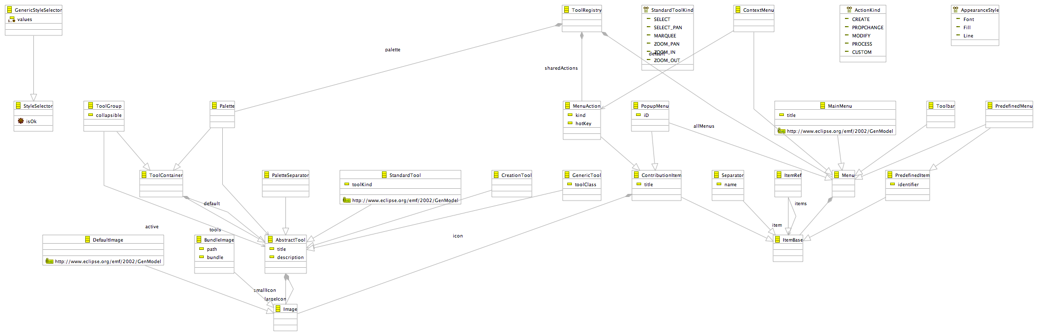
As mentioned above, the tooling definition model is used to specify the palette, creation tools, actions, etc. for your graphical elements. To the right is a diagram of the model.
The cheat sheet will guide you through a very similar process for getting started with our Simple Tooling Definition Model. In fact, the two steps are virtually identical, as the mindmap domain model is loaded and examined for possible tooling needs. We will simply select the same options we did for the graphical definition, save a tool for the Topic name label, and begin with a very simple palette for our Topic elements. 
Looking at the model provided for us, we see there is a top-level 'Tool Registry' element, under which we find a Palette. The palette contains a Tool Group with Creation Tool elements for both Topic nodes and links for subtopic elements that were identified by the wizard. We will reorganize these and modify them a bit in the future, but for now we'll leave the defaults and move on to the mapping definition. Feel free to browse this model and inspect its properties to familiarize yourself with tooling definitions.
Mapping Definition

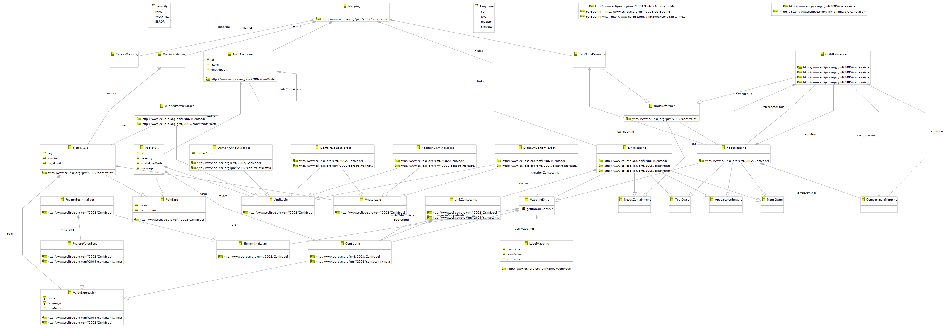
The mapping definition model will let us bind the three models we have so far: the domain, the graphical definition, and the tooling definition. To the right is an image of this model. This is a key model to GMF development and will be used as input to a transformation step which will produce our final model, the generation model.
Continuing on with our cheat sheet, follow the instructions to launch the Guide Mapping Model Creation wizard. We will again select the 'model' folder to hold our mindmap.gmfmap file and move on to load each of the preselected mindmap.ecore, mindmap.gmfgraph, and mindmap.gmftool models. On the next page, select 'Map' as the Diagram Root Element, accept the mindmapPalette from the selected tooling model, and then accept the selected mindmap diagram canvas. Finally, make the last page look like the image below. Note that you can adjust the properties for the selected node or link by using the 'Change...' button in the dialog.

style="CLEAR: both">

One thing we need to do manually is create a Label Mapping for our TopicNameLabel from the graphical definition. The result should look like the image to the right. While in the properties view, check the mapping of the TopicNode Node Mapping as well, to make sure it has the desired values. Actually, carefully check that the mapping wizard assigned the proper tool to both the Topic node and the Subtopics link until bug 189410 is resolved.
Before moving on, let's pause to describe the mappings. We'll start with the Label Mapping, as it's the one we're looking at here. It's a straightforward mapping, with the Diagram Label property set as we discussed and a mapping to the 'EAttribute name' feature on our Topic element in the domain model.
Moving up to the Node Mapping, we see that our Diagram Node is mapped to the TopicNode of our graphical definition with its corresponding domain model element mapped to our Topic class. The Topic creation tool is also specified in the mapping.
Above the Node Mapping you will find a Top Node Reference. Its Containment Feature is set to the 'EReference rootTopics' feature of our Map class. So, when new Topic nodes are added to the diagram, the instance of our domain Topic will be added to the rootTopics containment reference of our Map class. The label of the node will display the 'name' attribute of the Topic.
The Map class itself is represented by the Canvas. Select the Canvas Mapping element to see this defined, along with the map to the Palette in our tooling definition. Finally, if you select the Link Mapping, you will observe that connections represented by our TopicSubtopicsLink are mapped to the 'EReference subtopics' feature of our Topic class, and are created with our TopicSubtopics Creation Tool.
Tip : It is important to select the proper element when defining mappings at this stage; that is, before GMF does more complete filtering and validation. A good way to ensure you have selected the element you intended (as several may have the same name), open the mapping definition (*.gmfmap) file in a text editor, when in doubt.
Code Generation

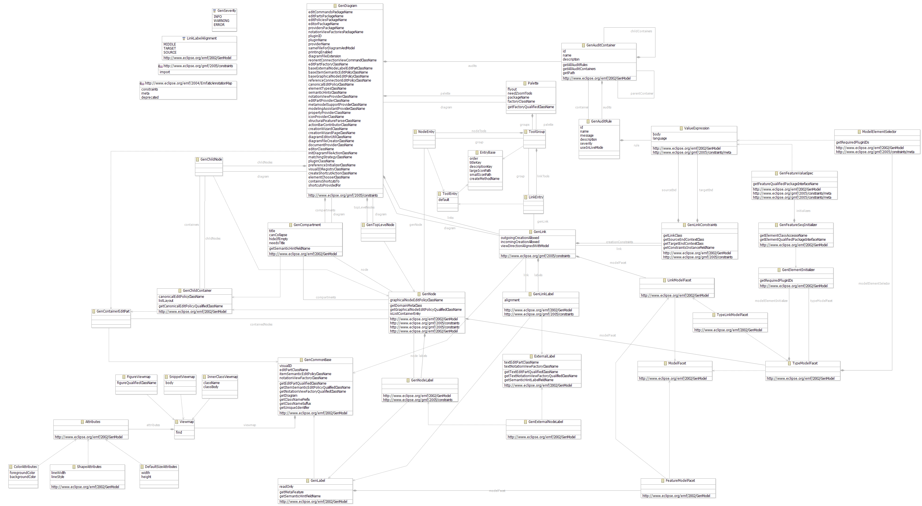
The last model to cover in this tutorial, and the one that is not as critical to understand at this point, is the GMF generator model. See the diagram to the right if you're interested in examining this model.
Now that the minimal graphical elements and mappings are defined, we can generate the code needed to test our work so far. To accomplish this, we will first create a generator model (*.gmfgen) in order to set the properties for code generation, similar to the familiar EMF genmodel. To accomplish this, right-click the mapping file and select 'Create generator model...' as shown below. When prompted, keep the default name 'mindmap.gmfgen'.
style="CLEAR: both">

Now, we can examine the generator model to see what it includes (if you're the curious type). We'll keep all the default values for now and right-click the mindmap.gmfgen file and select 'Generate diagram code' to proceed. If all goes well, you will see a "Code generation completed successfully." message dialog. Dismiss the dialog, opting to never see it again, and notice the new org.eclipse.gmf.examples.mindmap.diagram plug-in in your workspace.
Up to this point, the models used have been fairly straightforward to edit and understand. The transformation that takes place to create the generator model (*.gmfgen) from the mapping model involves a bit of logic that is important to understand. However, it is not required to understand the details at this point in the tutorial, so additional information can be found here for those interested.
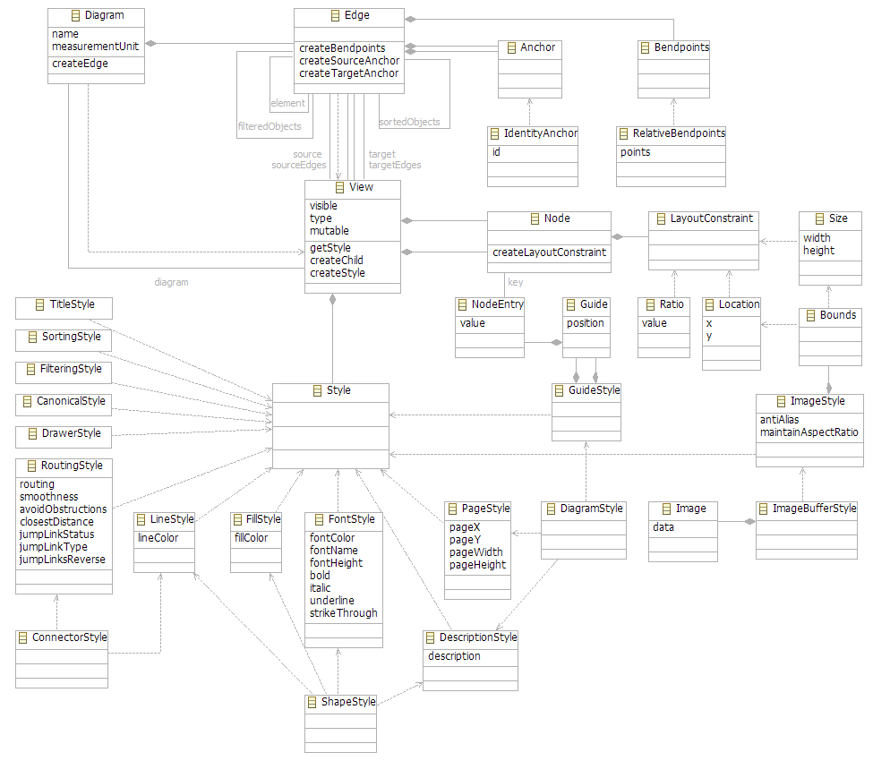
Running the Diagram

Recall that the runtime uses its own 'notation model' to display and persist the graphical components for your diagram. An image of this model is linked here for those interested.
Now that we have generated the plug-in needed for our diagram, let's launch a new runtime workspace and test the diagram. The default settings of a new Eclipse Application runtime configuration should work fine, while you may opt to run a minimal configuration that includes only your generated plug-ins and their runtime dependencies within an org.eclipse.platform.ide configuration.
Create an empty project and invoke the New... dialog (Ctrl+N). Under 'Examples' you'll notice your new Mindmap Diagram. Create a new diagram and explore its functionality, and look for the creation of the domain model instance as you add and save diagram elements. Of course, we've only specified enough in our diagram definition to allow for simple Topic elements and subtopic links.

Tip : If you'd like remove the icons from your labels (as shown here), try setting the 'Element Icon' property on your 'Diagram Label TopicNameLabel' element in your mindmap.gmfgraph model to 'false'. They are enabled by default.
Summary
As you have seen, using GMF as a means by which to get started creating graphical editors for your domain models is fairly straightforward. We have seen how creating a graphical definition and a mapping definition to the chosen domain can be used to generate much of the basic functionality expected in an EMF/GEF-based editor. In the future, GMF will mature and include more advance capabilities, so check back to see how this tutorial matures along with the project. In the meantime, if you've skipped over links that provide more detail on certain aspects of GMF, now may be the time to do so. Otherwise, feel free to continue with the GMF Tutorial Part 2.
References
- Eclipse Development using the Graphical Editing Framework and the Eclipse Modeling Framework, IBM Redbook
- Using GEF with EMF, Eclipse Corner Article
'Java > Eclipse' 카테고리의 다른 글
| [Eclipse][node] Cannot find module (0) | 2013.07.04 |
|---|---|
| Eclipse update error 이클립스 업데이트 에러 (0) | 2012.05.11 |
| 이클립스 플러그인 (0) | 2011.08.25 |
| Eclipse 3.5 - new features for Java developers (0) | 2009.07.21 |
| Eclipse 3.5 - new features in the Platform and Equinox (0) | 2009.07.21 |
| Eclipse 3.4 - New features in the Platform (0) | 2008.08.26 |
| Eclipse 3.4 - New features for Java developers (0) | 2008.08.11 |
 Rss Feed
